
In this video I’m going to take you through a walkthrough of the 55-ton compressor wall that you see behind me. This is a packaged rooftop configuration unit, although they are available in a paramount configuration or a wide variety of airflow configurations to meet your specific project. And we’re going to walk through really the six main sections of that unit plus the fluid cooler on the end and talk in depth about why we’ve made some of the design choices we have.
Let’s take a look into it right now in this first section of the air path through the unit. And that’s how we’re going to do this explanation of our technologies. We’re going to follow the process air through the unit. This is the return air section. So this is where hot, humid air is coming from your space and is eventually going to be filtered cool dehumidifiers. And then move back into your space. This first compartment here you see a bottom return air opening. So this is a unit that’s designed to be on the roof. Again, that return air opening can be left, right, top or horizontal. If it’s not packaged. But the air comes in, it gets filtered by the MERV 13 filters behind MERV.
13 filters remove many contaminants, including things like fungal spores from your air stream. So it’s an important part of the bio safety of your facility. You’re also going to notice in this compartment something that’s a little unusual, and we’ll talk about that or the why in compartment two. But there’s a second pump in this compartment, and that’s for our economize our loop.
And again, we’ll talk about the details of of the how and why in the second compartment, but these are fast load filters, very easy to change, obviously recommending that change happen between every flower cycle or roughly every eight to ten weeks in a non-flower space. Very important obviously to keep those filters clean to ensure efficient airflow through your unit.
Let’s move on now to the economize section. In this section, we’ve got the economy as our coils. And this is a compartment that is quote unquote nonstandard in the base configuration of the unit. But one of the advantages we have in using dry coolers and our fluid loop for heat rejection is we can run those dry coolers in the winter and use those dry coolers effectively to produce chilled water and so that’s what this unit is equipped with.
And that is the section you see behind me. There’s three economize are coils, and they effectively operate as chilled water coils. Any time the outdoor air temperature is below about 50 degrees ambient in that 50-degree condition, these coils are offering free cooling and they increase the moisture removal efficiency of the compressor pods that are right behind them.
Once you get below about 35 degrees outside, these coils are capable of doing all of the cooling and dehumidification of the equipment and can offer a very, very efficient cooling and dehumidification solution when the outdoor air conditions support it. So in this way we’re able to do a true economize or cooling system without the introduction of any outside air and without the contamination risk.
That second pump that was in the return air section is to create that second chilled water loop. And it’s a loop that is entirely separate from the compressor heat rejection loop or I guess the heat rejection loop bleeds into that loop in order to have a cold loop and a hot loop. And we’ll talk about the hot loop again, one section further on, but that allows us again with our internal controls to control the chilled water function or the economize or function and the heat rejection function in a simultaneous way.
All of the controls for this are internal. There’s nothing that you need to do as a customer or as an installing contractor to get this to work. Its built in. It gets put on site and it works. Again, our real goal there is to make it make the integration of this equipment the start-up of this equipment as easy and as seamless as possible.
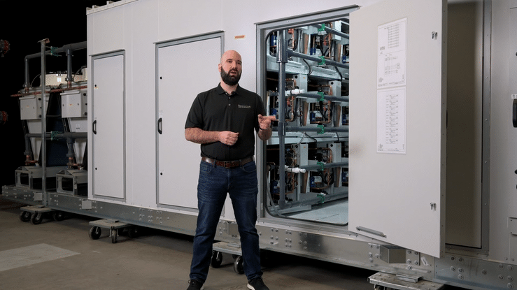
In this section behind me, we’ve got both the compressor pods, the hydraulic reheat coils and the pump to make the whole system work. Now, one of the brilliant things about the compressor, well, technology is our reliance on a hydraulic loop for both heat rejection and for the reheat coils. And it’s really the reason we’re able to do multiple small circuits in a cost effective and controllable way by dumping all of the compressor waste heat into that hydraulic loop, we’re able to fully modulate between the reheat coil and heat rejection outside and achieve 100% heat rejection to either the process Airstream in reheat or dehumidification mode or outside of the dry cooler in air conditioning mode or proportionally between those two. And that allows us to achieve a very, very tight space temperature control. And as a result of humidity being relative to temperature by a team achieving a tight temperature control, we can very tightly control relative humidity. One of the other things you’ll see on this door right behind me are electrical diagrams for this compartment.
And these are inside the door for every compartment. And it’s another thing that we do just to allow our equipment to be that much more serviceable, that much easier to work on by your local mechanical contractor. By our service techs and by your maintenance guy onsite. Let’s take a look at the parts in this other side. Now of that same section you’ll see behind me the nine compressor pods that make up the 55-ton unit.
Our compressor wall technology uses multiple small refrigeration pods, either 6.3 or 7.6 nominal tons, and uses them in multiples to create whatever nominal tonnage the facility needs. Again, this 55-ton unit using nine of them, the product line itself goes all the way down to a ten ton unit using only two pods to a 120 ton unit using 16 of them.
And what that means for us is we’ve got a very repeatable process. We’ve got the same size refrigeration system ultimately being used across in multiples across a huge range of our product line. It’s very efficient to build, it’s very efficient for us on a supply chain perspective from a quality assurance perspective. But it also means that you as the customer, whether you’ve got an application that needs a 90-ton unit or a 24-ton unit, the fundamental technology behind it feels very familiar and ultimately you have the same pods and both of those systems it means that your maintenance guys, your mechanical contractor, they can become familiar with their technology and work on any of it.
You’ll notice behind me that we’ve also got relatively small coils. And then again, the purpose behind that is you can get a lot of compressor tonnage in relatively small coils this way and eliminate any moisture carryover and ensure that we’ve got a positive draining happening between the compound drain pads behind me. We’ll take a look at the cutaway because I can talk a little more freely about how that technology all looks together and show a picture of what 120 tons of these pods looks like.
It’s pretty impressive. But ultimately this 55-ton frame size behind me is about the sweet spot for us and generally for the customer base. So to my right here, you see one of the individual compressor pods that makes up all of our compressor wall units. These pods are available in two sizes. They’re physically the same dimension, but just with a different compressor capacity And again, that 6.3 or 7.6 ton size that we multiply out to achieve the breadth of product line that we have here’s a typical configuration of how they’re put together.
This is a six-pod show wall, but what we’ve got here are 66.3 ton pods that make up our 36 ton compressor wall. Each of those pods is electrically independent and has an individual waterside disconnect that allows you to remove it from the loop without draining the hydraulic loop and allows the reheat assembly to work properly. The built-in pump and mixing valves allow us to circulate that water for cooling and reheat flow as well as control and modulate between the reheat coil and the dry cooler for heat rejection.
Each one of these pods is using electromechanical speed or a capacity reduction technology. These are the Copeland’s EPS to stage compressors. That electromechanical capacity reduction is very reliable, very robust, and in low speed mode. These are mostly sensible pods and then in full speed or full capacity, we add in the late and cooling. So the sensible cooling being the air conditioning part and the latent cooling being the dehumidification.
And in that way and on an individual basis, we’re able to tailor the cooling and dehumidification to the room demands in real time, ensuring that we’re not overdrawing or over cooling air space, but applying just the right amount of work. And it’s a big part of why we’re the most efficient solution to this space. In the second to last airflow compartment, you’ll see behind me the three backdraft dampers, one for each fan these dampers automatically close in the event of a fan failure ensuring and plus one airflow redundancy.
The other part of this section is the electric heater, and that electric heater is interlocked with the compressors to ensure that we’re not taking an MLP penalty to have it in there, but provides emergency heat. If you ever need it. Generally speaking, the electric heater is only there if the facility is cold and dark for whatever reason or suffers a power outage or for first time start up, it is not required because of our full size hydraulic reheat for the day-to-day operation of that unit, ensuring a very efficient overall system.
So take a look now at the electrical compartment. So here we are on the electrical panel of this unit again. 55 tonne unit, you can see a very clean layout in the high voltage panel, an integrated disconnect to ensure that it’s very easy for your electrical contractor to complete their install work. That disconnect handle is a through the door style ensuring again you’re electrically safe before you open it.
And then as part of our continuous improvement process and improving the customer experience, we’ve recently started separating the high voltage and low voltage cabinets. What that means is that you can work on the low voltage components and keep the high voltage components isolated and live but with no electric shock hazard. And so again, that’s the part of our ensuring that we’ve got continuity of care for your plants and that the environment that those plants are in is always maintained.
Here we are at the last section of the process air journey through our machine, and this is our fan compartment. Every unit we ship, whether it’s classic evolution or compressor wall, has direct drive plenum fans as it’s air mover technology of choice. In fact, the only air mover technology we use, these fans provide high static, low noise, and very high airflow efficiency.
And each fan is also equipped with airflow monitoring on these compressor wall units, meaning that you can set an air flow value and the unit will turn up or down the fans based on filter loading or based on coil wetting or any of a half dozen other things that would affect your overall airflow. That allows you to get very consistent airflow through your space, a very consistent environment in your space, ensuring that there’s no stratification or any of the other sort of typical temperature problems that you’d find in this compartment as well.
Again, you see the three redundant fans we talked to already about the backdraft damper on the front of those fans. There’s an air proving switch and then just a personal safety great ensuring that nobody has the opportunity to fall through the machine into the building in the event of servicing. That’s the end of the airflow section. Let’s go take a look at deregulation.
Here I am in front of the dry cooler section of this 55-ton piece of equipment, and this is a packaged unit, which means that the dry cooler is attached to the system factory filled, ready to go from us. And so there’s no site work that needs to be done to get cooling. Working on this equipment. We’re using a dry cooler and a water glycol mix for our heat rejection for two reasons, and one is it allows us very fine control between outdoor heat rejection through the dry cooler and the reheat.
And again, we talked about the hydraulic reheat loop earlier when we were talking about the pod section. But two is using a water glycol mix for heat rejection allows us to entirely isolate our compressor circuits from the outdoor ambient condition, which means that we can operate reliably in any outdoor ambient condition down all the way to -40 degrees.
And that’s a real boon in this industry, particularly because standard track equipment in the low ambient condition really starts to struggle, particularly when you’re looking at condenser-based units with reheat, because you end up with multiple condensers and flooded condenser problem and liquid slugging and low pressure trips. As a result, there’s a variety of bad things that happen to refrigeration circuits in the low ambient condition and having the glycol completely isolates that from happening.
These coils are seacoast coated, so you’ll see that blue coating behind me. That’s a salt spray rated coating. So these can be appropriately applied anywhere in North America, whether you’re right on the coast or you’re more inland. And that provides a great corrosion protection for that coil, ensuring a long lifespan. We’ve also got modulating fans on top of it.
And so those fans will turn up or down zero to 100% based on the Heat rejection need that the system is seeing at any given point. So we don’t have to speed or single speed fans banging on and off. It ensures a much quieter operation and a much more reliable circuit temperature, which ensures that our refrigeration circuits can be much more stable and much more reliable.
There’s a whole bunch of good reasons that we do the dry cooler as our primary heat rejection. I’ve gone through some of them. We’re going to talk about the balance of them. In the dry, cooler, specific video, but that is the end of the overview here. Of the 55 ton. I hope you’ve learned something about this piece of equipment.
And again, if you have any questions about it or its application or any of our other product line features, please get in touch with us. We’d be happy to work with you on your project.